
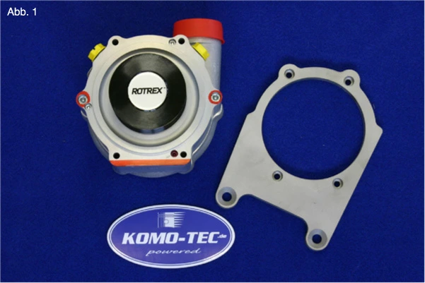
The weight of the supercharger, the forces generated by its drive, and engine vibrations require a stable mounting of the supercharger. A plate (e.g., made of high-strength aluminum or “stainless steel”) can be secured using the 4 mounting screws that connect the supercharger housing and the gearbox housing, through which all forces are transmitted. (see also Fig. 1)
To ensure a continuous oil supply to the planetary gear, the Rotrex supercharger should be installed such that
The correct design of the drive system has a significant impact on
the performance
the efficiency
the service life
the ease of maintenance
of the entire system
The gear ratio of the supercharger must be selected such that, at maximum engine speed, the maximum permissible rotor speed of the selected supercharger is not exceeded.
The diameter of the pulley DPL on the supercharger is calculated as follows:
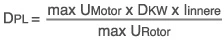
DPL = Diameter of the pulley on the loader (mm)
max UMotor = Maximum motor speed (rpm)
DKW = Diameter of the pulley on the crankshaft (mm)
Iinnere = Internal gear ratio of the loader (planetary gear)
max URotor = maximum rotor speed (see “Technical Data Sheet”)
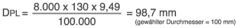
Example:
max UMotor = 8,000 rpm
DKW = 130 mm
Iinnere = 9.49 (C30-94)
max URotor = 100,000 rpm (C30-94)
Modern internal combustion engines primarily use V-ribbed belts to drive auxiliary components (alternator, air conditioning compressor, power steering, etc.). A common size is the “6 PK,” a V-ribbed belt with 6 ribs. This type of belt, which is available in a wide range of lengths, can transmit high drive power. When the overall system is properly designed, this belt type is sufficient for driving standard Rotrex superchargers. The power that a V-ribbed belt can transmit depends largely on the wrap angle of the pulleys. If the transmissible power is 100% at a wrap angle of 180°, the maximum transmissible power is reduced to just 64% at, for example, 80°.
In addition to the Rotrex supercharger, the correct drive of the alternator in particular depends on a large wrap angle of the pulley. Modern alternators require high drive power, especially when high-power consumers (seat heating, windshield heating, etc.) are switched on. (See also www.contitech.de – Industry)
3. Boost Pressure Control
Selecting the “right” turbocharger size determines the boost pressure curve across the entire RPM range and its maximum value at high RPMs.
Experience has shown that, in modern high-performance engines, boost pressures between 0.4 and 0.5 bar are sufficient to generate a power increase of approximately 30%. To control the rise in boost pressure at high RPMs, mechanically/pneumatically or electrically controlled bypass valves can be used. These valves divert a portion of the airflow downstream of the turbocharger through a “bypass line” back to the inlet, thereby reducing the pressure.
In practice, however, “throttle nozzles” at the turbocharger inlet have also proven highly effective. When properly designed aerodynamically, these nozzles have only a minor effect on boost pressure build-up at medium RPMs, but very effectively limit the maximum pressure at high RPMs. These nozzles react very sensitively to changes in diameter in the range of a few tenths of a millimeter. They thus represent a simple, practical method for boost pressure control.
Closing the throttle valve at high RPMs leads to a sharp pressure buildup upstream of the throttle valve, which, combined with a low flow rate, pushes the supercharger to its so-called “pumping limit.” This causes the flow to partially separate from the supercharger blades. Even though Rotrex superchargers, thanks to their design, are only damaged by “pumping” in exceptional cases
Closing the throttle valve at high RPMs causes a significant buildup of pressure upstream of the throttle valve, which, combined with a low airflow rate, pushes the turbocharger to its so-called “pumping limit.” As a result, the flow partially separates from the turbocharger blades. Even though Rotrex superchargers, thanks to their design, are only damaged by “pumping” in exceptional cases, the resulting noise and the engine’s running characteristics during coasting and at low throttle angles are unacceptable. A so-called “pop-off valve,” which diverts the high boost pressure away from the supercharger, must therefore be provided.
Complete documentation available as a PDF download