
As a rule, the engine tuner does not have all the necessary engine specifications required to precisely define the turbocharger’s parameters. Since the computational effort should also be kept within reasonable limits, the result must be considered a guideline. Some mathematical and physical simplifications are deliberately accepted in this process.
Step 1: Target engine power
(Example: The naturally aspirated engine’s 200 hp is to be increased to 300 hp)
Step 2: Calculation of the air flow rate AF
Modern high-performance engines “consume” approximately 0.0009 kg of air per hp per second. Thus, the air mass flow rate AF is given by: AF = Planned engine power × Air flow rate per second
(Example: 300 hp × 0.0009 kg/hp/sec. = 0.27 kg/sec.)
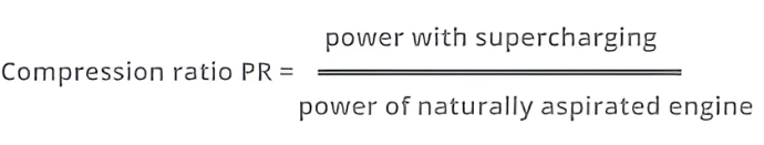
Step 3: Calculating the pressure ratio PR
Since the power of an internal combustion engine increases proportionally to its air flow rate, the required pressure ratio must now be determined. The power of the naturally aspirated base engine and the planned power of the turbocharged engine thus behave, as a first approximation, like the air flow rates of the two variants.
The power required to drive the Rotrex supercharger, flow losses in the intake system and the intercooler, and the rise in charge air temperature combine to result in a “loss factor” of approximately 15%. This results in an effective pressure ratio of:
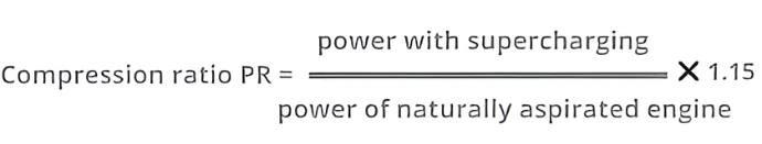
(Example: (300 hp : 200 hp) x 1.15 = 1.1725 pressure ratio PR eff)
Step 4: Transfer the calculated values to the pressure-flow rate map (flow chart)
The “flow charts” for the various supercharger models show:- the “islands” representing the supercharger’s efficiency.- the corresponding supercharger speed- the so-called “pump limit” of the supercharger (left line)
A vertical line is drawn from the airflow rate AF determined in Step 2. (Example: AF = 0.27 kg/sec) A horizontal line is drawn from the pressure ratio (PR) value determined in Step 3. (Example: PR = 1.725) Now a pressure-volume characteristic curve (flow chart) must be found where the intersection of the lines lies as close as possible within an “island” of maximum efficiency.
(Example: AF = 0.27 kg/sec and PR = 1.725 intersect in the diagram of the C30-94 supercharger within the “island” of maximum efficiency of 80% and at a moderate supercharger speed of approximately 80,000 rpm)
Complete documentation available as a PDF download